Back to work

The Royal Swedish Opera

Wheel Unit

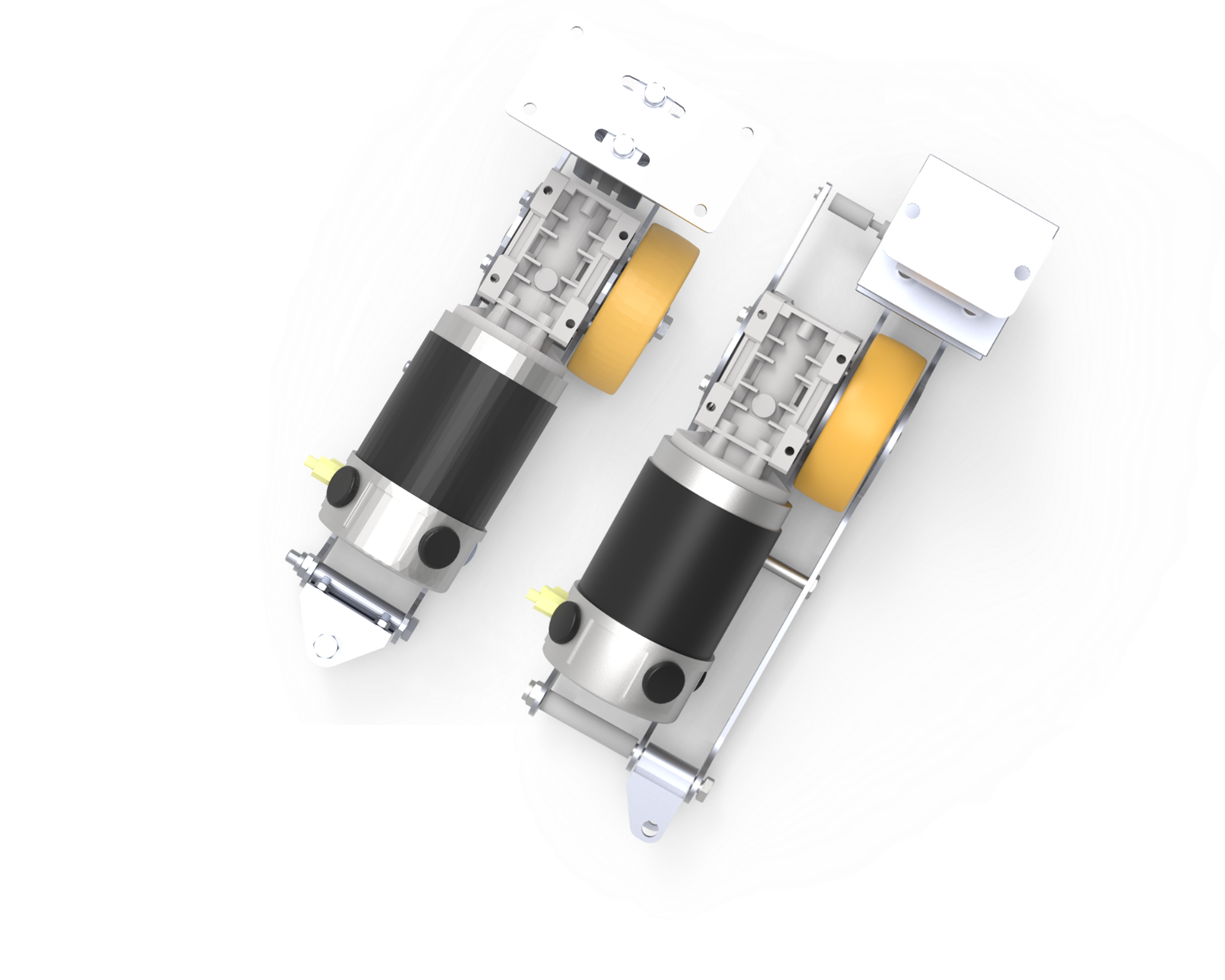
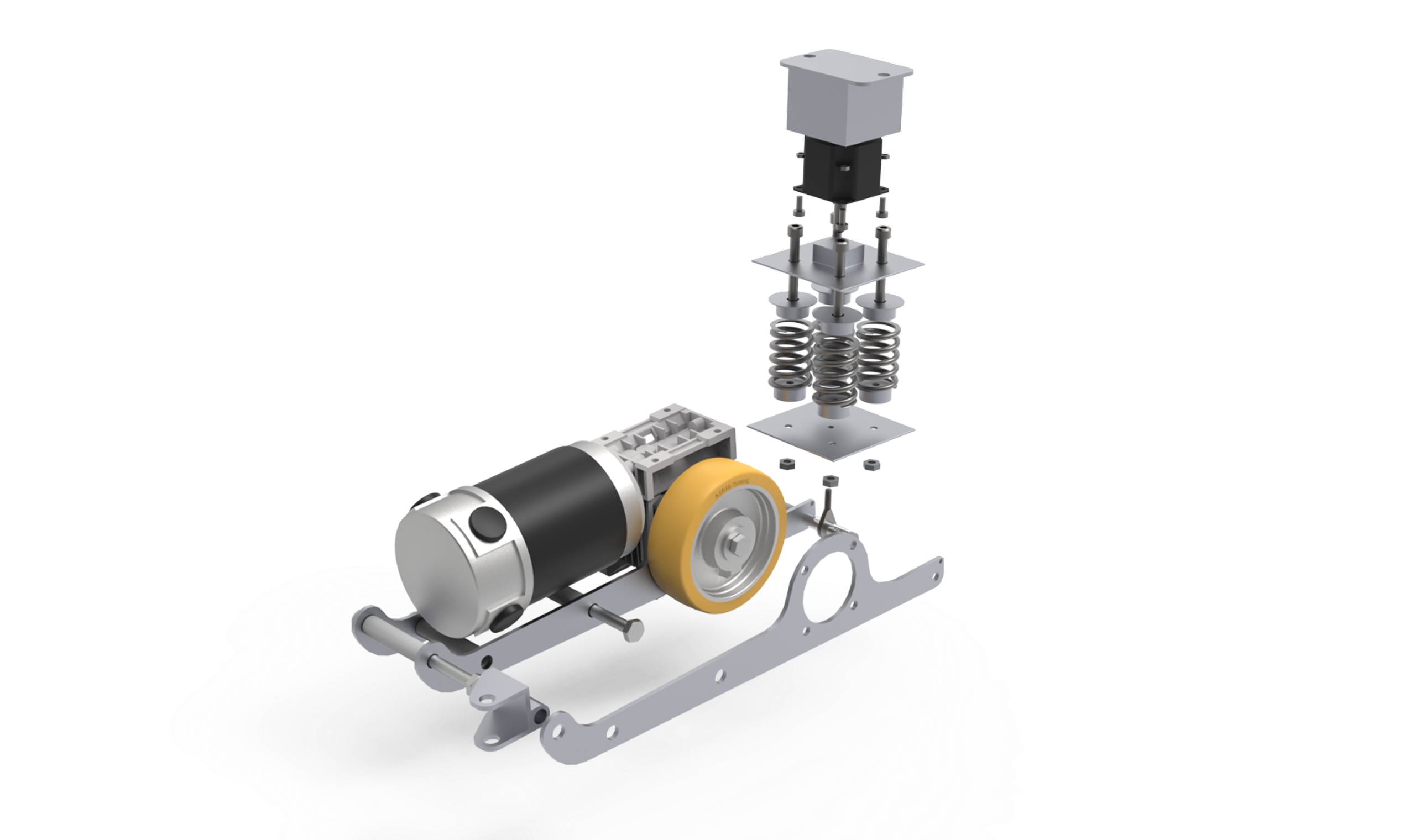
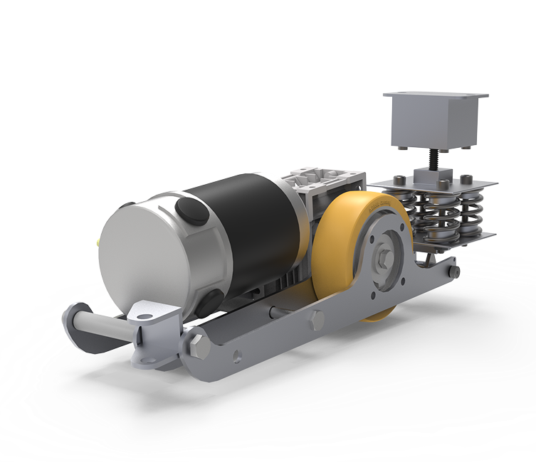
Driven by increasingly complex stage designs, the Royal Swedish Opera (Kungliga Operan) needed to redesign their existing 'Wheel Unit.' This motorized wheel is used to both remotely control the movement of heavy set pieces on stage and actuate a lifting mechanism to lock them securely in place. The legacy solution relied on a confusing and potentially unsafe hybrid of electric and pneumatic systems. The brief was to overhaul the unit, focusing on a purely electrical solution that prioritized user safety and intuitive operation.

Wheel Unit project image

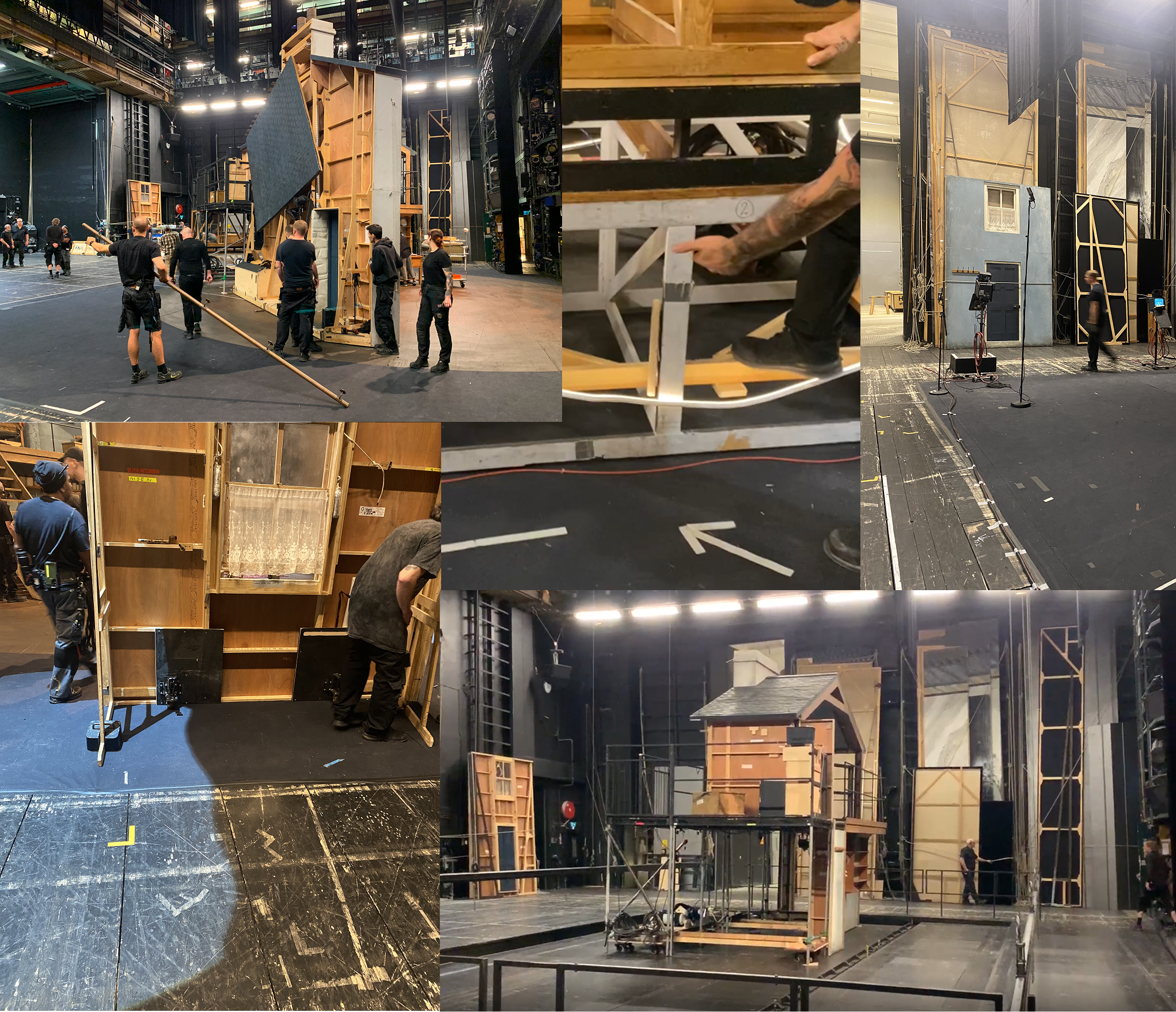
On-site research

We were invited backstage during a live performance to observe the crew both during the high-stress intermission scene changes and after the show. Witnessing this hectic environment firsthand made it clear that the new unit had to be incredibly reliable and intuitive enough to operate on "autopilot." Interviews with the stage technicians provided critical insights into the real-world flaws of the existing unit.

Risks & technical requirements

Operating with stage scenery weighing up to 4,000 kg meant that any mechanical malfunction could have catastrophic consequences. Together with the Royal Swedish Opera, we conducted an extensive risk assessment. A core requirement was a fail-safe braking system: the unit's default state must always be locked unless active input is given. Additionally, the opera's stage floor features a 4% incline. This constraint added significant complexity, as every calculation and simulation had to account for the resulting lateral force components acting on the unit.
Brake system

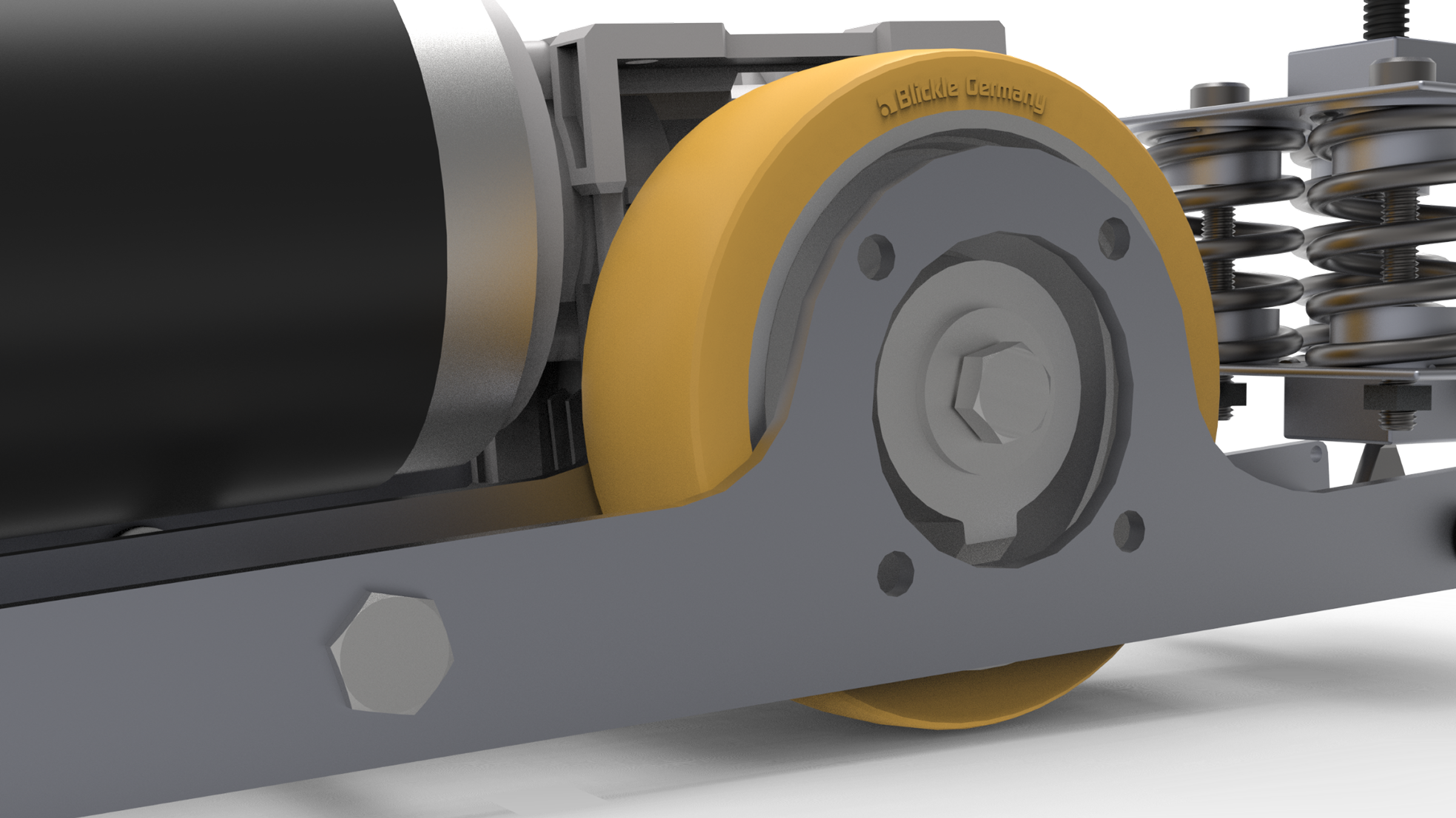
After analysing the forces of the worst case scenario (that being their heaviest decor), and a large safety factor, the resulting forces required to brake the wheels was calculated. For larger set pieces, four wheel units are used and since they use a self-locking worm gear, that proved enough to lock the wheels. The friction coefficient was calculated in case the wheels would start sliding, but given the material of the wheels, it was safe from this as well.

Brackets

The old system was attached in the centre line of the unit. This caused a torque in the wheel which caused it to ever so slightly veer to the side. To accommodate for this, the attachment point was moved to be in line with the wheel itself, and a third bracket was installed to stabilise it. While the motor itself now contributed to some torque, the amount was almost negligible compared to the force that came from the decor.

The lift & lower system

After evaluating various concepts, including scissor lifts and sliders, the legacy pneumatic system was replaced with a robust lead screw mechanism. In this new architecture, the unit's main chassis acts as a traveling nut, "climbing" as the lead screw rotates.

Driven by a programmable stepper motor, the system precise-counts its rotations to know exactly when the wheel reaches the ground. This turned a previously unpredictable, manual guessing game into an intuitive, single-button operation. To ensure the housing could withstand the immense loads of the scenery, rigorous material selection and Finite Element Analysis (FEA) were conducted.

The suspension system

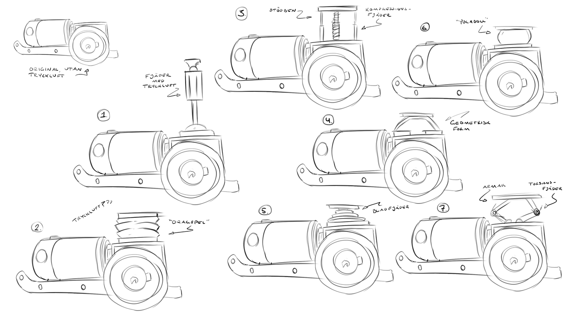
Eliminating the pneumatics meant losing the inherent cushioning they provided. A new suspension was critical, as the historic stage floor can unevenly deviate by up to 20 mm. Following an extensive ideation phase, a dedicated spring assembly was developed.

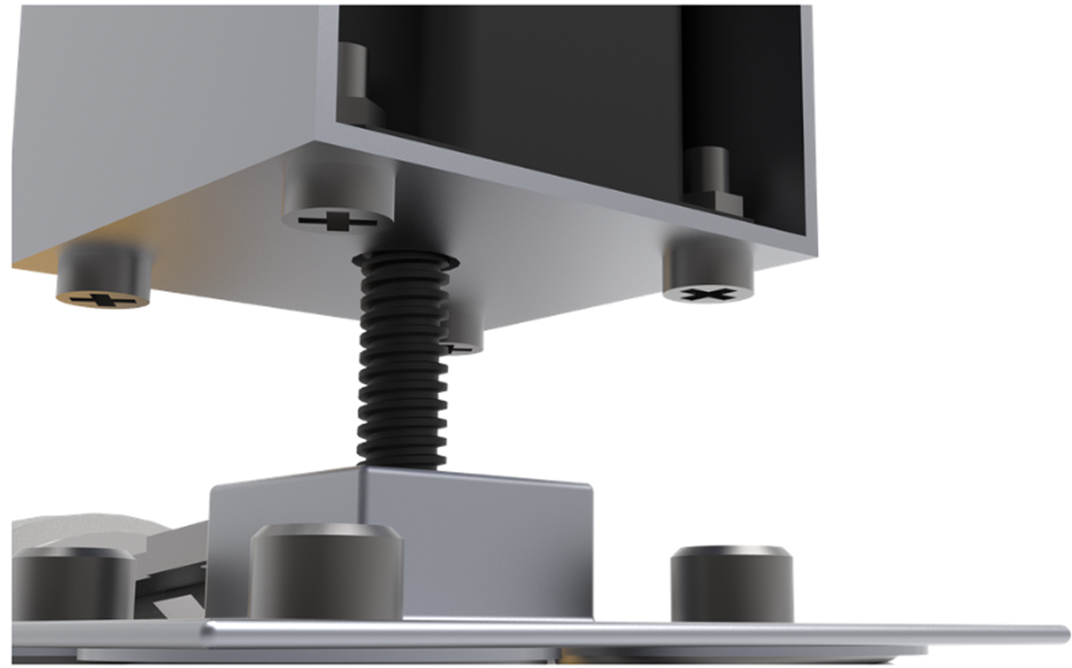
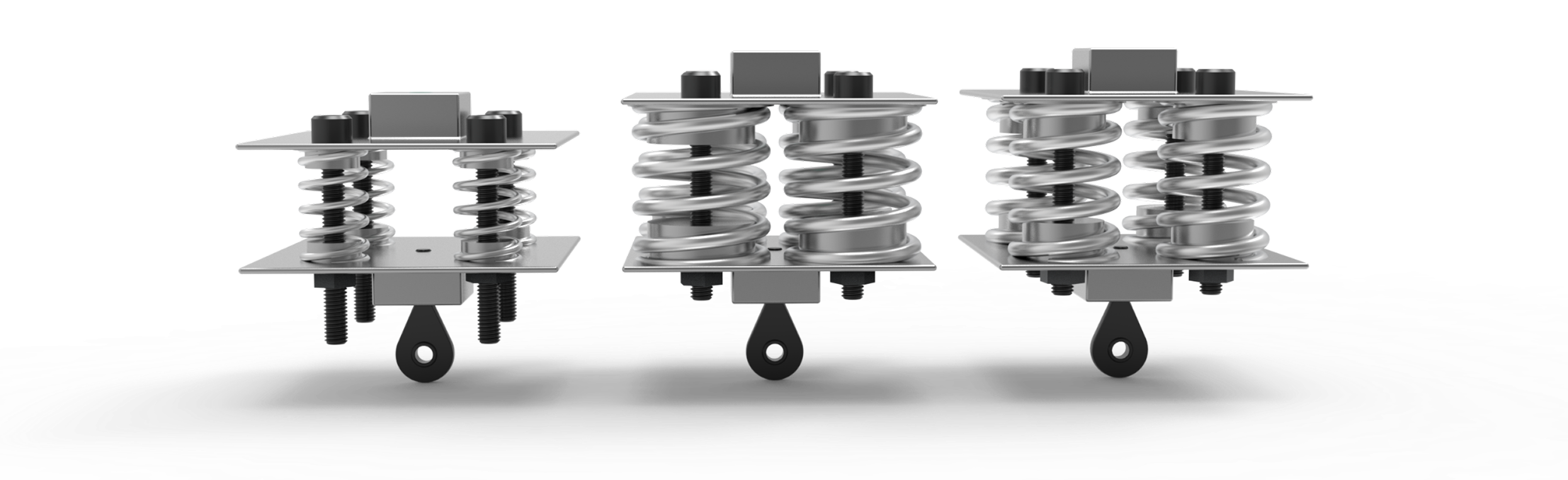
The assembly features four guided springs that can be pre-loaded via adjustment screws to match the specific weight of the scenery. To accommodate drastic weight variations, three interchangeable spring packages were designed. At the base, a ball joint connects the assembly to the main body, allowing the lead screw and suspension to pivot freely during actuation.

Hero